
Nascom continued 1
Here is a link to the Nascom schematics again as a reference.
At this point, when I build the boards below, my Nascom still existed as the original board. The board was roughly the size of a DIN A4 sheet of paper. With the help of the Z80 buffer and the parallel bus cards shown here, I was able to move the Nascom piece by piece to a card system consisting of a couple of 100x160mm cards.
One of the first cards I rebuild carried the parallel interface to the keyboard and the UART. The UART serialized the parallel data into a bitstream and vice vera. With some extra circuitry, it was the main component to allow the backup and restore of your precious data to and from a cassette recorder.
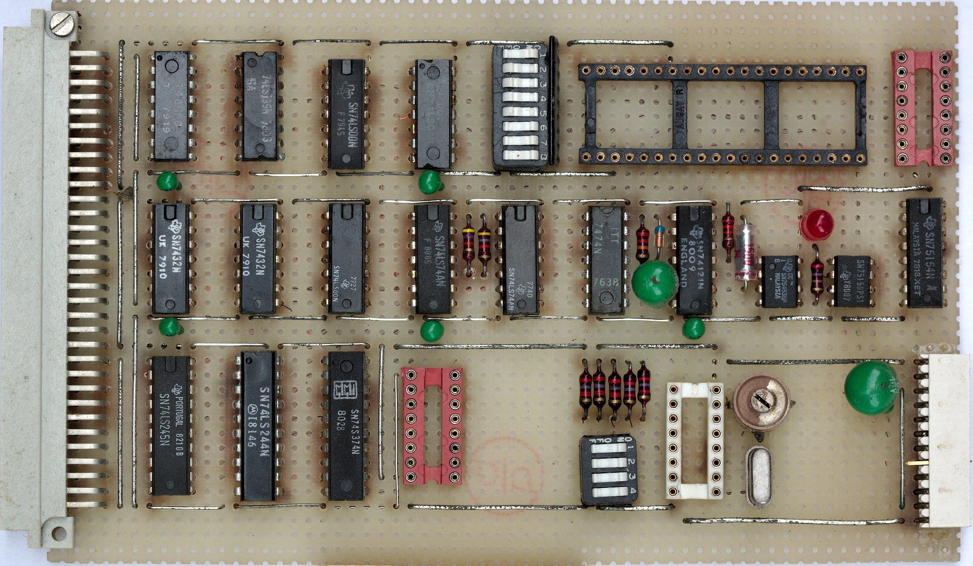
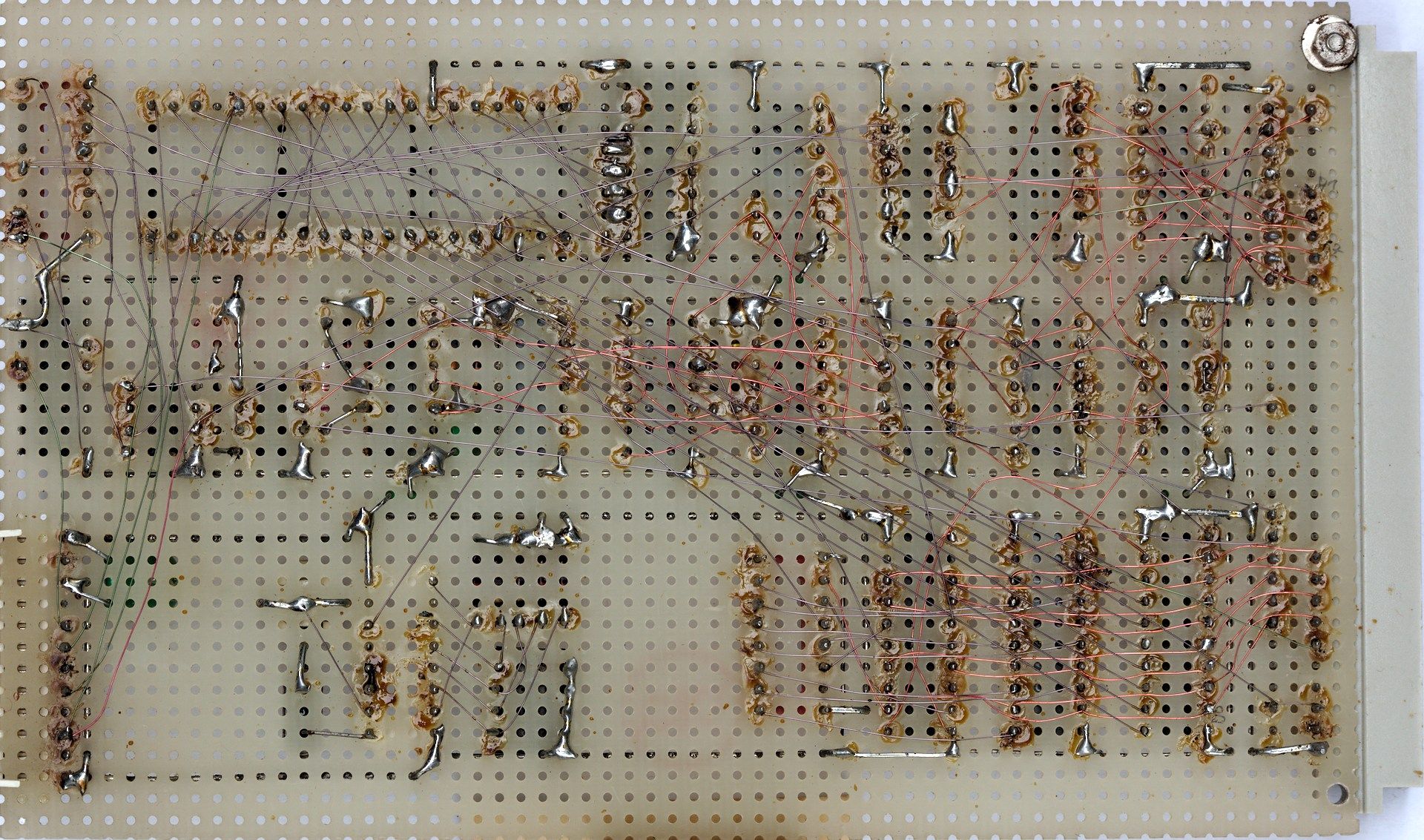
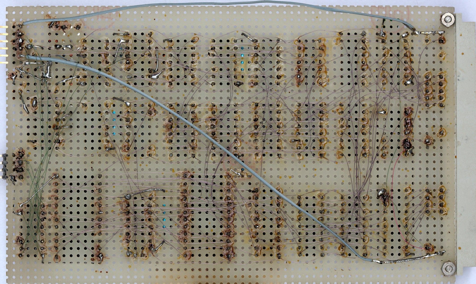
Looking at the backside of the board, it’s not really beautiful, but it works very well. In the end, my complete system was built with this wire wrap technique. The most important thing for this kind of build is good bookkeeping. Each connection must be marked, once it’s created. Otherwise, the overview is quickly lost.
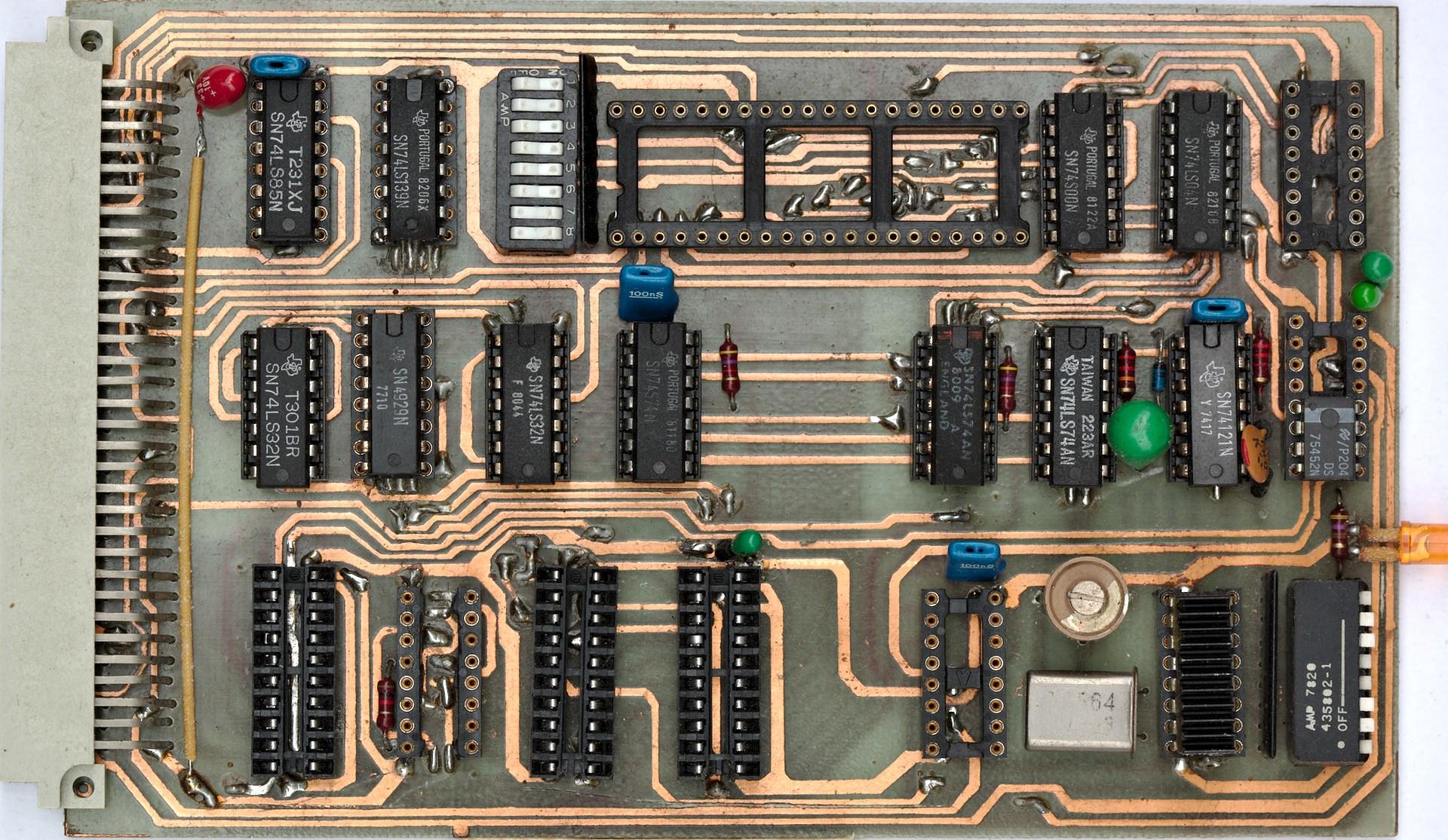
Later I recreated the board once again. This time, I manually routed a double sided printed version (see above) and etched it.
Next step was to put all the video logic on one card.
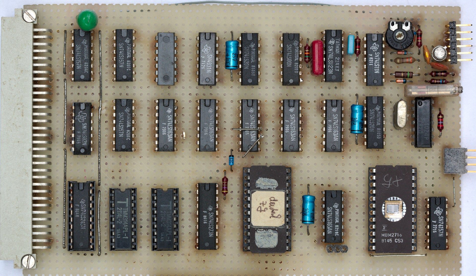
During this time period 7bit ASCII was the standard encoding. The German umlaut characters (üöäÜÖÄ) were typically mapped into the locations of the curly and square brackets. So I put two character generator EPROMs on this board, one for English and one for German characters. The two largest chips in the above picture are the character generator EPROMs.
These chips could be electrically programmed. Later they could be erased by shining ultraviolet light through the round window above the actual chip.
The next board design contained the first significant improvements compared to the original NASCOM design. It was in use until I stopped using the Z80 system.
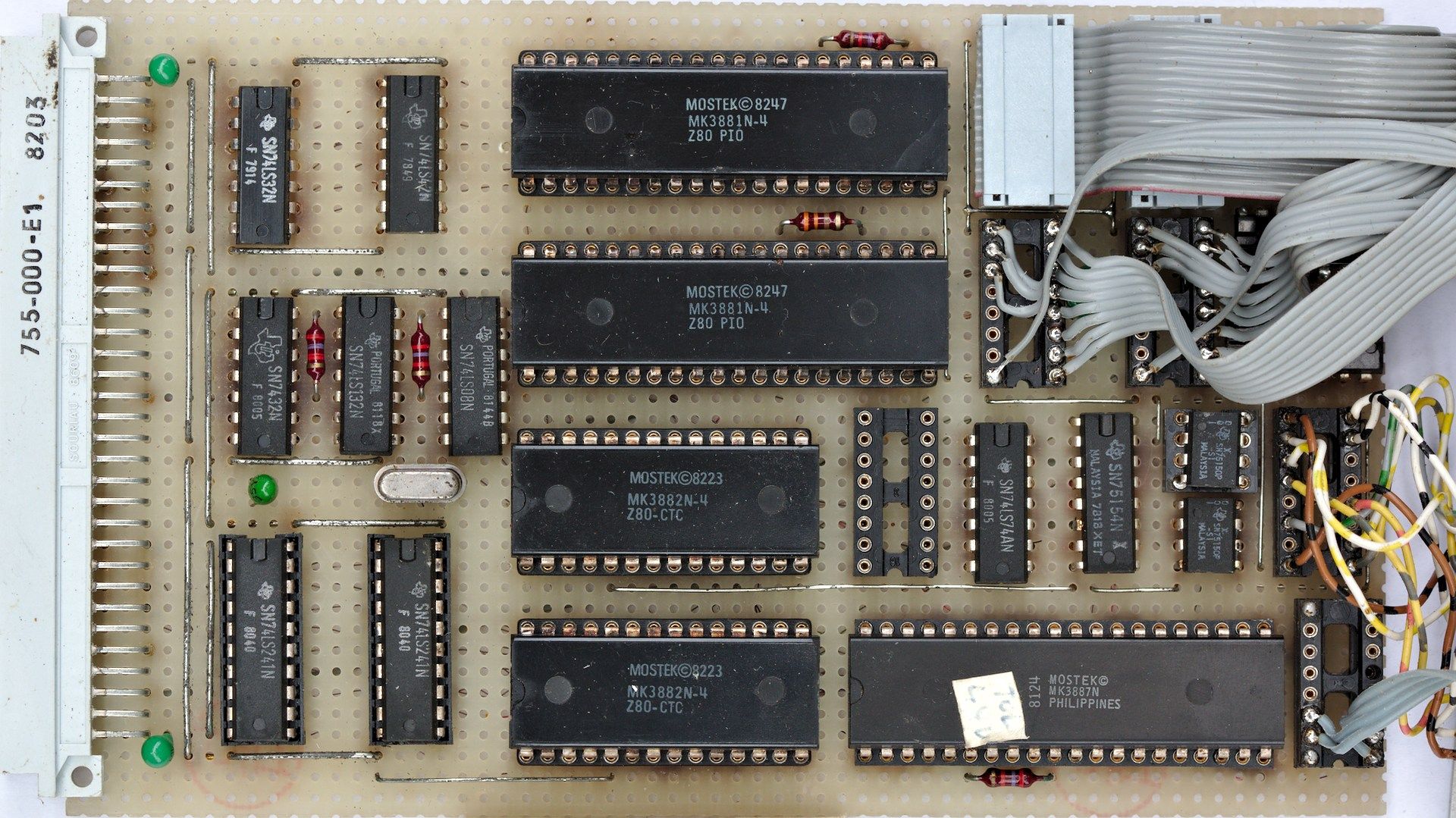
This card carried two parallel input/output chips (Z80 PIOs), two counter/timer chips (Z80 CTC) and one serial input/output chip (Z80 SIO). One of the CTC chips is used as the baud rate clock generator for the SIO.
The Centronics-style parallel printer interface was realized through the top PIO. The parallel keyboard interface was later converted to serial and moved to the SIO. I was able to locate the appropriate code places in the original NASCOM monitor software. I replaced it with code redirecting any keyboard interaction to the Z80 SIO.